For the complete documentation index, see llms.txt. This page is also available as Markdown.

Device Setup

This chapter describes the setup procedure for the card reader and controller in the following sections:

Selecting Unit Location

Use the following guidelines when selecting a location for your device.

  • Select a location convenient for the customer.

  • Avoid dusty, hot or damp locations.

  • To minimize data reading or writing errors, pick a location free from magnetic interference. Choose a spot a safe distance away from objects or units that generate magnetism.

  • Install the unit not more than 0.5 m away from the UX400 CTLS Reader.

Choosing Mounting Location

Choose a mounting location that ensures the card slot is in full view of the cardholder during card insertion.

The front panel of the device meets the IP34 standards for installation under outdoor environments.

Unpacking the Shipping Carton

Open the shipping carton and carefully inspect its contents for possible tampering or shipping damage.

  1. Remove the unit from the shipping carton. The standard package contains the unit, a grounding cable and a ferrite connector cable for connecting to an external power supply. Refer to Accessories and Documentation for more information about the device's related accessories.

  2. Remove any protective wrap before mounting the unit.

  3. Save the shipping carton and packing material for future repacking or moving of the device.

Examining the Unit's Features

Before you continue the installation process, review the features of the device (see Figure 1, Figure 2 and Figure 3).

Figure 1: UX300 Front View

Front Features

The front of the reader shows the following:

  • Customer-view indicator LEDs

  • The card reader slot

  • Anti-removal switches

  • Installation mounting stud holes.

Figure 2: UX300-Petrol Underside View

Verifone ships variants of the UX300 for different markets. Your unit may have a different configuration and may look different from the illustrations in this guide. However, the basic process described in this guide remain the same, regardless of the configuration.

Please refer to Specifications for details on all UX300 models.

Underside Features

  • Nozzle for water drainage

  • Persistent board (UX300-Petrol) features:

    • USB Device (Type B) [client]

    • Powered USB (Type A) [host]

    • Power port 12 V DC

    • LAN with 2 LEDs

    • COM1 (RS-232)

    • 8-PIN RF port

    • SMA (analog RF) CTLS / NFC antenna connector.

  • Model-dependent board features:

    • UX300-MDB

      • MDB power port

      • Two RS-232 powered ports

      • Four USB Type A master ports

    • UX300-PSTN

      • MDB power port

      • One RS-232 powered port

      • Four USB Type A master ports

      • PSTN port

    • UX300-ISDN

      • MDB power port

      • ISDN port

      • One RS-232 powered port

      • Four USB Type A master ports

    • UX300-GPRS

      • MDB power port

      • One RS-232 powered port

      • SIM card slot

      • Four USB Type A master ports

      • GPRS antenna port

    • UX300-Petrol

      • Power Port, DC-In, DC-Out, (24 V DC)

      • Two RS-232 powered ports

      • Four USB Type A master ports

      • RS-485 port

    • UX300-LAN

      • MDB power port

      • Two RS-232 powered ports

      • Four USB Type A master ports

      • Second LAN port.

    • UX300-WPWR

      • Power Port (24 V DC)

Figure 3: UX300 Top View

Top Features

The following illustration shows the top view of the UX300.

  • SAM card slots

  • System Mode service switch

UX300 GPRS Bottom Functions

  • Nozzle for water drainage

  • Persistent board connection ports:

    • USB port (Type B) [client]

    • High-powered USB (Type A) for UX PIN pad connection [host]

    • Power port

    • LAN with 2 LEDs

    • COM1

    • 8-PIN connector to UX400 CTLS antenna unit

    • SMA (analog RF) CTLS antenna connector to UX400

  • UX300 Model-dependent board ports:

    • MDB Power port

    • COM port

    • SIM Card slot

    • Four USB Type A ports (one high-powered slot)

  • GPRS antenna

Figure 4: UX300-GPRS Bottom View

ARS and Service Switches

The following illustrations show the locations of the two Anti-Removal Switches (ARS) and the service switch on the UX300.

Figure 5: UX300 ARS and Service Switches

Removal Protection

The front Anti-Removal Switches (ARS) detect any removal attempt from the device cabinet and disables the PIN processing functionality. Re-installation requires an authorized process. Please contact your Verifone representative for details.

System Mode Activation

The rear service switch gives administrators System Mode access for the UX300. Use only if you have the proper authorization and equipment to open system mode. Please contact your Verifone representative for details.

Installing or Replacing SAM Cards

You may need to install a security access module (SAM) card or replace the old card. You can find two SAM slots on the UX300, located under a removable protective cover (see Figure 6).

  1. Disconnect the device from all power sources.

  2. Disconnect the device from any external devices.

  3. Slide the SAM cardholder cover away from the unit, off the top panel.

Figure 6: Removing the SAM Cardholder Casing
  1. Open the SAM cardholder by sliding the locking tab towards the back of the unit, to the OPEN position.

  2. Carefully slide the SAM card into the slot, by aligning the card and carefully sliding into the slot until fully inserted.

Before inserting the SAM card, position it as shown in Figure 7, with the card's gold contacts facing outward, toward the unit. The cardholder connector base has a set of contacts and a notch to ensure the SAM card is positioned correctly. The SAM card has a notch on one corner to ensure that it fits into the connector base in only one way.

  1. Close the SAM cardholder.

  2. Slide the locking tab to the LOCK position.

Figure 7: Installing the SAM Card
  1. Slide the cardholder cover back, locking it into place.

Figure 8: Replacing the SAM Cardholders

Normal Operation Mode

Do not use the UX300 unless it is in normal operation mode. By default, the position of the toggle switch located on the side of the SAM compartment is set to High. There are cases where the switch is moved especially when the device is sent for servicing and upgrade. When this happens, use a tweezer or a similar tool to toggle the switch back to High. To make sure that the switch is in High position, the switch must be aligned with the number 1 located beside the SAM slot as shown in the illustration below.

Figure 9: Toggle Switch Set to High Position
Installing SIM Card and Antenna

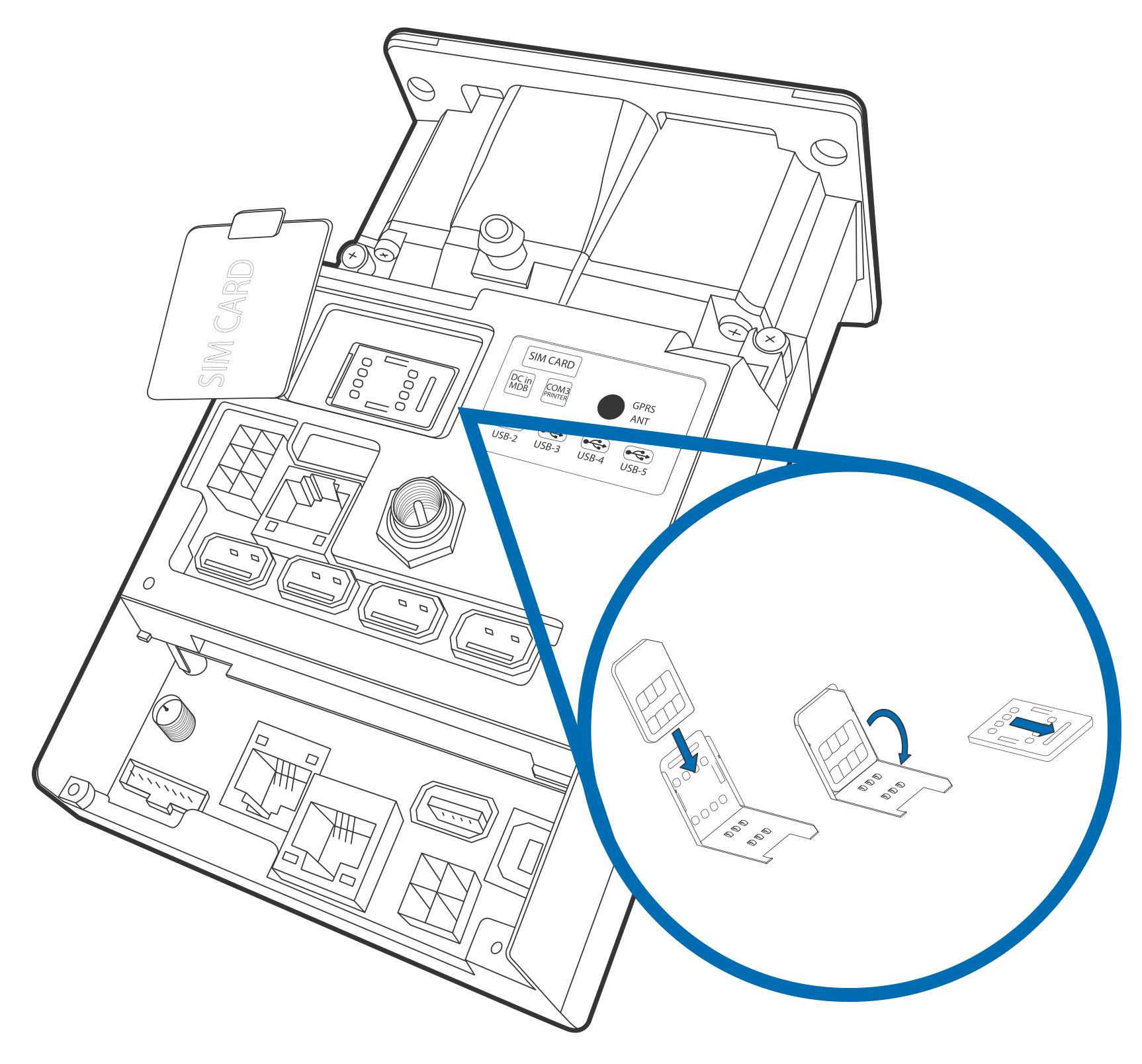
The UX300-GPRS unit supports the installation of a GSM SIM (Subscriber Identity Module) for fast, always on connectivity. Use the following procedure to install a SIM card and attach the GPRS antenna.

  1. Disconnect the device from all power sources.

  2. Disconnect the device from any external devices.

  3. Lift up and twist the rubberized SIM Card cover to the side.

  4. Open the SIM cardholder by sliding the locking tab towards the back of the unit, to the UNLOCK position.

There is only one GSM SIM slot. Before inserting the SIM card, position it as shown in the illustration, with the card's gold contacts facing the compartment. The cardholder connector base has a set of contacts and a notch to ensure the SIM/RUIM card is positioned correctly. The SIM card has a notch on one corner to ensure that it fits into the connector base in only one way.

  1. Carefully slide the SIM card into the slot, by aligning the card and carefully sliding into the slot until fully inserted.

Figure 10: Inserting the SIM Card
  1. Close the SIM cardholder.

  2. Slide the locking tab to the LOCK position.

  3. Replace the rubberized SIM Card cover.

  4. Attach the GPRS antenna (VPN ANT159-300-01-A) by screwing the base to the antenna port on the UX300. Tighten to the recommended torque of 7.0 kgfcm.

Cable Connections

The UX300 rear panel holds several interface ports for power and communications. Use this section to see how the UX300 connects to various UX-series units, as well as other devices.

To get the proper connection cables, please refer to Accessories and Documentation.

Connecting to a UX-Series Host Device

This section discusses the connection of the UX300 device with the following host units:

Connecting to a Vending Machine

You can connect the UX300 to a host vending machine (VM) with any of the following connection types:

  • USB Type B

  • ETH (LAN)

  • COM (RS-232)

  • MDB

Connecting to a PC

You can connect the UX300 to a host PC with any of the following connection options:

  • RJ45 to RS-232 connection

  • USB Type B connection

  • LAN connection

For more information regarding your card reader configuration and your cabling needs, contact your local Verifone service provider. For cable ordering information, see Accessories and Documentation.

Connecting to a UX-Series Peripheral Device

This section discusses the connection of the UX300 device with the following peripheral units:

Connecting to a UX1xx Series PIN Pad

You can connect the UX300 to a UX1xx-series PIN pad device with a standard USB Type A to B connection (VPN CBL000-045-01-A).

Figure 11: Connecting to a UX110 PIN Pad

Connect the Type A plug in the UX300 high-powered port and connect the type B plug to the USB port of the UX110. Use the same procedure for connecting to other UX1xx-series PIN pads.

Connecting to a UX400 CTLS Unit

You can connect the UX300 to a UX400 contactless unit using an 8-pin to RJ45 cable (VPN CBL159-301-01-A) and an SMA connector (VPN CBL159-302-02-A).

  1. Connect the 8-pin connector to the UX300 and connect the RJ45 plug to the UX400. Make sure both devices are not more than 0.5 m away from each other.

  2. Attach one end of the SMA cable to the UX300 and the other end to the UX400.

Figure 12: Connecting to a UX400 CTLS Unit

Tighten the SMA cable at both ends by holding the end cap and turning. Avoid holding the strain relief cord while tightening the end caps.

The UX300 host device installs the UX400 upon startup.

Connecting Optional Devices

The UX300-Petrol can connect to various peripheral devices outside of the UX-Series product range.

Connecting to a TG-2460H Printer

You can connect a UX300-Petrol unit to an external printer, such as Verifone's TG-2460H printer, using a combination RS-232 to RJ45 cable (VPN CBL159-305-01-A).

  1. Disconnect the device from all power sources.

  2. Disconnect the device from any external devices.

  3. Connect the RS-232 cable to the UX300-Petrol printer port and connect the RJ45 plug to the printer.

Figure 13: Connecting TG-2460H Printer Cable
  1. Connect power to the printer using the CBL159-306-01-A and 28580-01-R cables.

Figure 14: Connecting Power to UX300-Petrol and Printer

Disconnecting Cables

To disconnect cables, use the same steps described above in reverse. If exchanging cables, use Verifone-approved cables. See Accessories and Documentation for cable part numbers and ordering information.

Installing USB Cable Retainers

After connecting peripherals and other devices to the UX300, you can secure USB cables by installing retainers (VPN SUB159-305-01-A). Use the following steps to install the cable retainers.

We recommend using Verifone USB cables (see Accessories and Documentation) for uniformity in cable connector sizes.

To install USB cable retainers:

After you connect USB cables to the UX300, install the following retainers to secure the cables in place.

Figure 15: Installing First Two Cable Retainers
  1. Position the main cable retainer on the lip of the persistent board. See A in Figure 15.

  2. Place the three-pronged cable retainer over the two USB cables on the persistent board. See B in Figure 15.

  3. Fasten two hex screws to hold down the two retainers. See C in Figure 15.

Figure 16: Installing Third Cable Retainer
  1. Slot the third retainer's legs in the holes of the main retainer, over the installed USB cables on the model-dependent board. See D in Figure 16.

We recommend using Verifone USB cables (see Accessories and Documentation) for uniformity in cable connector sizes.

  1. Swing the retainer down to lock in place over the USB cables and make sure the screw holes align with the main cable retainer. See E in Figure 16.

  2. Secure the retainer with two hex screws to lock the USB cables in place. See F in Figure 16.

Mounting the Device

Use the following procedure to mount the UX300 to a suitable mounting surface.

Your mounting surface may have different installation instructions. Refer to the user guide of your mounting device for further information.

To mount the unit:

  1. Align the UX300 stud holes with the holes on the mounting surface.

Figure 17: Mounting the UX300
  1. Place the reader flush onto the mounting slot.

  2. Secure the unit with M5 nuts with a minimum length of 12 mm. Tighten the nuts using to the recommended torque of 7.0 kgfcm (6.1 lbf.in).

You can also mount the UX300 using welded screw bolts on the inner side of the mounting plate. This prevents any vandalism of the screw heads on the outer surface.

  1. Connect flexible tubing with 9 mm inner diameter to the drain nozzle at the bottom of the UX300 (see Figure 2) and place the other end of the tubing at an appropriate drainage area.

The nozzle drains water out of the bezel area through the flexible tube. Ensure that the tubing is properly dressed and mounted as vertical as possible, without any loops, to ensure smooth water drainage.

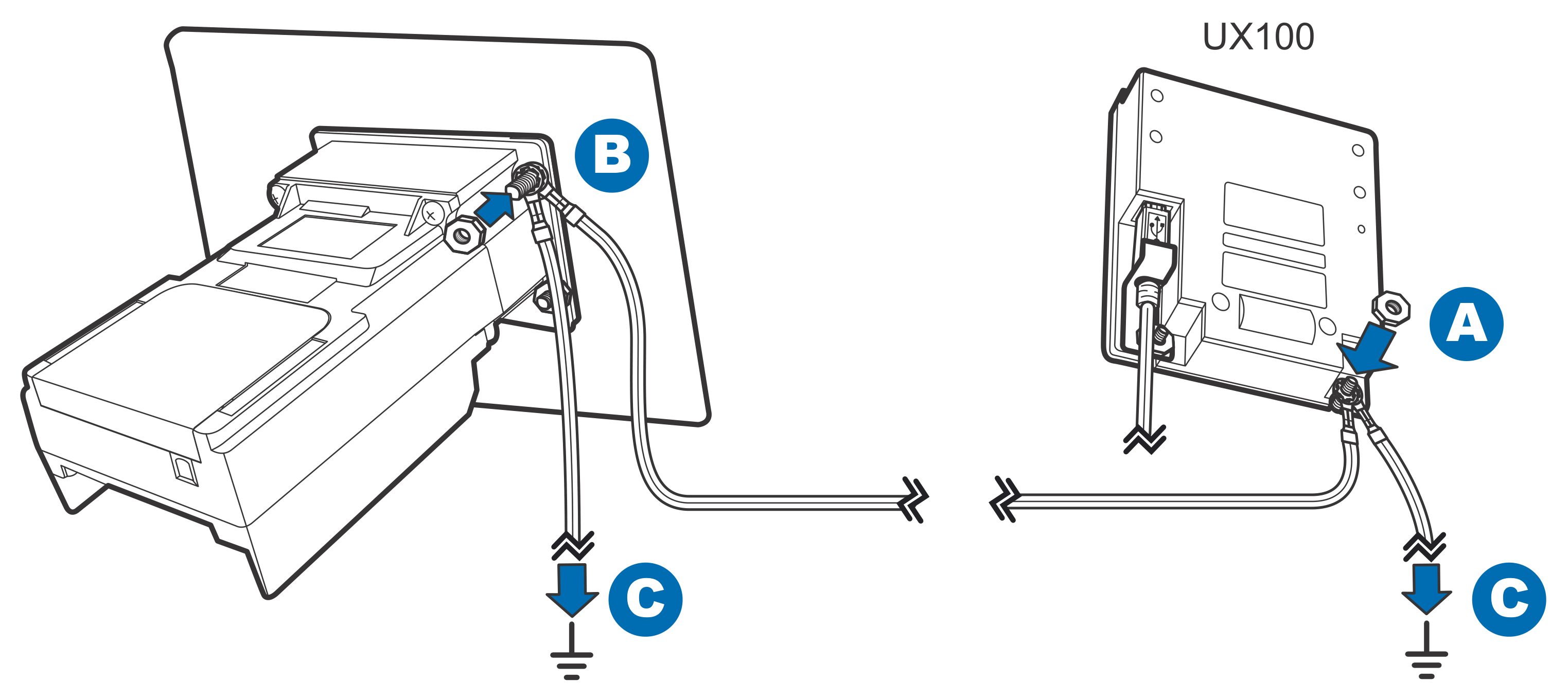
Grounding the Units

If you connect the UX300 to a UX-series PIN pad, use the following steps to ground your units.

For cable use and ordering information, see Accessories and Documentation.

To ground the units:

  1. Remove mounting nuts from the back of the UX300 and the PIN pad unit. Do not remove the nut securing the PIN pad cable retainer.

Figure 18: Grounding the UX300 and PIN Pad Units
  1. Attach one end of the grounding cable (VPN WIR159-302-02-A) to the UX300 and connect the other end to a ground installation. See (C) in Figure 18.

  2. Use another grounding cable (VPN WIR159-302-02-A) and attach one end to the PIN pad mounting bolt. Connect the other end to a ground installation. See (C) in Figure 18.

  3. Connect the UX300 to the PIN pad with another grounding cable (VPN WIR159-302-01-A) using the same mounting bolts. See (A, B) in Figure 18.

  4. Replace the nuts and tighten to the recommended torque of 7.0 kgfcm (6.1 lbf.in).

Connecting Power Supply

Not all UX300 configurations and device contexts require the use of a power supply. Verifone ships power supplies with the UX300 as required.

If you have questions about which power supply to use, contact your Verifone representative. For more information, see Accessories and Documentation.

Attach and route all cables between the UX300 and all peripheral units before connecting to the power source.

To protect against possible damage caused by lightning strikes and electrical surges, Verifone recommends installing a power surge protector.

Power Connections

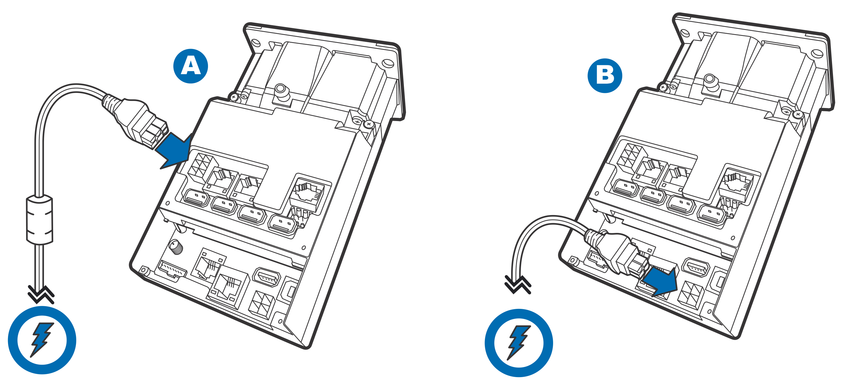
The UX300 connects to external power in the following ways:

  • With a 4-pin cable (VPN CBL159-308-01-A) from the power port on the persistent board (see A in Figure 19), or

  • With a 6-pin cable (VPN CBL159-309-01-A) from the power port on the model-dependent board (see B in Figure 19).

Your power connection depends on your specific card reader configuration.

Verifone ships variants of the UX300 for different markets. Your unit may have a different configuration and may look different from the illustrations in this guide. However, the basic process described in this guide remain the same, regardless of the configuration.

For more information regarding your card reader configuration, contact your local Verifone service provider. For cable ordering information, see Accessories and Documentation.

To connect to a power source:

Connect the power cable to the power port on the UX300 and the other end to your power source.

Figure 19: Power Connection Options for the UX300 Series

Using the Device

Card transaction procedures vary depending on the application. Verify the proper procedure with your application provider before performing a card transaction.

Using the Multi-Card Reader

The UX300 supports magnetic stripe cards as well as smart cards. Use the following steps in conducting UX300 card transactions.

To conduct a card transaction:

Position the card with the magnetic stripe facing downward and to the right of the card, or with the chip on top of the card and towards the card slot (see Figure 20).

Figure 20: Using the Multi-Card Reader
  1. If using a magnetic stripe card, insert the card fully into the slot, then remove the card in a smooth continuous motion.

The LEDs or peripheral display will indicate if the transaction is complete.

With magnetic stripe cards, card removal usually completes the transaction.

  1. If using a smart card, insert the card and follow the on-screen instructions before removing the card.

Last updated

Was this helpful?