Device Setup
This chapter describes the setup procedures for the UX301 card reader and controller.
Selecting Unit Location
Use the following guidelines when selecting a location for your device.
Select a location convenient for the customer.
Avoid dusty, hot or damp locations.
To minimize data reading or writing errors, pick a location free from magnetic interference. Choose a spot a safe distance away from objects or units that generate magnetism.
Install the unit not more than 0.8m away from the UX401 CTLS Reader.
Choosing Mounting Location
Choose a mounting location that ensures the card slot is in full view of the cardholder during card insertion.
Make sure the installation method does not invalidate the Anti-Removal Switch (ARS) function. Do not, for instance, install the UX301 in a sub-chassis that can be removed from the main cabinet.
Unpacking the Shipping Carton
Open the shipping carton and carefully inspect its contents for possible tampering or shipping damage.
To unpack the shipping carton:
Remove the unit from the shipping carton. The standard package contains the unit, a grounding cable and a ferrite connector cable (VPN CBL159-309-01-B) for connecting to an external power supply. Refer to Accessories and Documentation for more information about the device's related accessories.
Remove any protective wrap before mounting the unit.
Save the shipping carton and packing material for future repacking or moving of the device.
Do not use a unit that has been tampered with or otherwise damaged. This unit comes equipped with tamper-evident labels. If a label or component appears damaged, immediately notify the shipping company and your Verifone representative or service provider.
Examining the Unit's Features
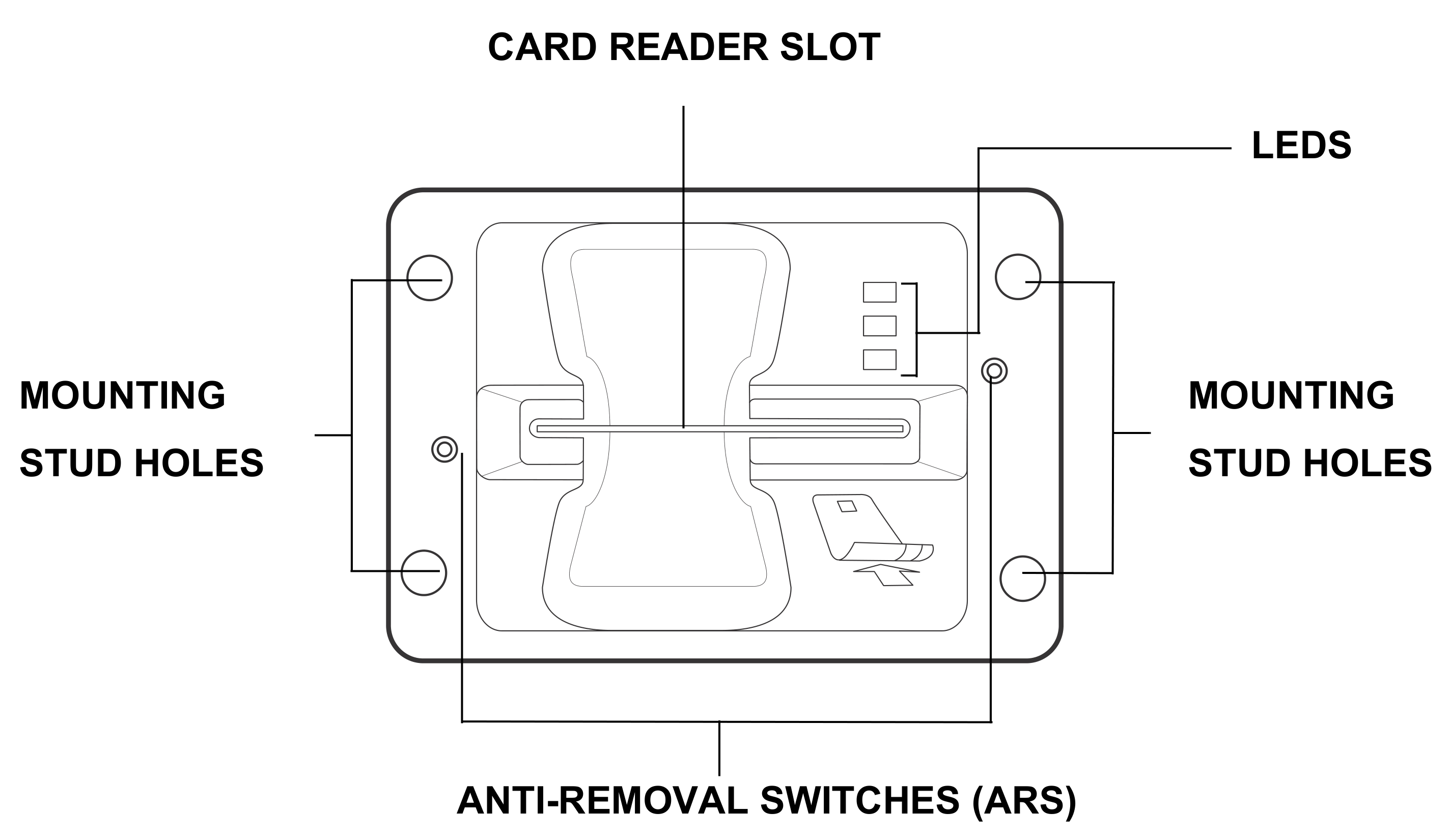
Before you continue the installation process, review the features of the device (see Figure 1, Figure 2 and Figure 3).

Front Features
The front of the reader shows the following:
Customer-view indicator LEDs
The card reader slot
Anti-removal switches
Installation mounting stud holes.

Back Features
Nozzle for water drainage
Persistent board features:
USB Device (Type B) [client]
2 Powered USB ports (Type A) [host]
Power port (9 to 43V DC Power in)
LAN with 2 LEDs
COM1 (RS-232)
8-PIN RF port
SMA (analog RF) CTLS / NFC antenna connector
3 SAM card slots
Model-dependent board features:
MDB power port (9 to 43V DC).

ARS and Service Switches
The following illustrations show the locations of the Anti-Removal Switches (ARS) and the service switch on the UX301.

Removal Protection
The front Anti-Removal Switches detect any removal attempt from the device cabinet and disables the PIN processing functionality. Re-installation requires an authorized process. Please contact your Verifone representative for details.
Make sure the installation method does not invalidate the Anti-Removal Switch (ARS) function. Do not, for instance, install the UX301 in a sub-chassis that can be removed from the main cabinet.
System Mode Activation
The rear service switch provides administrators System Mode access to the UX301. System Mode is restricted to administrators and authorized users only. Please contact your Verifone representative for details.
Installing or Replacing SAM Cards
You may need to install a security access module (SAM) card or replace the old card. You can find three SAM slots on the UX301 (see Figure 3).
Observe standard precautions in handling electrostatically sensitive devices. Electrostatic discharges can damage the equipment. Verifone recommends using a grounded anti-static wrist strap.
To install or replace SAM cards:
Disconnect the device from all power sources.
Disconnect the device from any external devices.
Carefully slide the SAM card into the slot, by aligning the card and carefully sliding into the slot until fully inserted.


Install additional SAM cards in the available slots as necessary.
Cable Connections
The UX301 rear panel holds several interface ports for power and communications. Use this section to see how the UX301 connects to various UX-series units, as well as other devices.
Connecting to a UX-Series Host Device
This section discusses the connection of the UX301 device with the following host units:
Connecting to a Vending Machine
You can connect the UX301 to a host vending machine (VM) with any of the following connection types:
USB Type B
ETH (LAN)
COM (RS-232)
MDB
For more information regarding your card reader configuration and your cabling needs, contact your local Verifone service provider. For cable ordering information, see Accessories and Documentation.
Connecting to a UX-Series Peripheral Device
This section discusses the connection of the UX301 device with the following peripheral units:
Connecting to a UX1xx Series PIN Pad
Connecting to a UX401 CTLS Unit.
Connecting to a UX1xx Series PIN Pad
You can connect the UX301 to a UX1xx-series PIN pad device with a standard USB Type A to B connection (VPN CBL000-045-01-A).

Connect the Type A plug in the UX301 high-powered port and connect the type B plug to the USB port of the UX110. Use the same procedure for connecting to other UX1xx-series PIN pads.
Connecting to a UX401 CTLS Unit
This section discusses connecting the UX301 device with the UX401 using UX301-UX401 comm cable (VPN CBL159-313-02-A) and a UX301-UX401 RF analog cable (VPN CBL159-302-03-A).
Do not enable the CTLS function by SW if the UX401 antenna isn't connected to the UX301.
Activating CTLS without a UX401 antenna attached can damage the UX301 RF front end.
To connect the UX301 to a UX401 CTLS unit:
Attach one end of the RJ45 plug cable to the UX301 and the other end to the UX401.
Attach one end of the SMA cable to the UX301 and the other end to the UX401.

Connecting Optional Devices
The UX301 can connect to various peripheral devices outside the UX-Series product range.
Connecting to a TG-2460H Printer
Use the following cables to connect to the UX301 to a TG2460-H printer:
Y-cable (VPN CBL159-306-01-A)
TG2460-H printer power cable (VPN 28580-01-R)
RS-232 cable (VPN CBL013-005-01-A).
To connect to a TG-2460H Printer:
Disconnect the device from all power sources.
Connect the RS-232 cable to the UX301 printer port and connect the RJ45 plug to the printer.

Connect power to the printer using the CBL159-306-01-A and 28580-01-R cables.

Disconnecting Cables
To disconnect cables, use the same steps described above in reverse. If exchanging cables, use Verifone-approved cables. See Accessories and Documentation for cable part numbers and ordering information.
Mounting the Device
Use the following procedure to mount the UX301 to a suitable mounting surface.
For proper operation of the Anti-Removal Switch (ARS), do not use additional gaskets or washers. Use the unit and its accessories as they are upon removing from the packaging.
Make sure that your mounting frame has a thickness of 2 mm.
To mount the unit:
Align the UX301 stud holes with the holes on the mounting surface.

Place the reader flush onto the mounting slot.
Secure the unit with M5 nuts with a minimum length of 12 mm. Tighten the nuts using to the recommended torque of 7.0 kgfcm (6.1 lbf.in).
Connect flexible tubing with 9mm inner diameter to the drain nozzle at the bottom of the UX301 (see Figure 2) and place the other end of the tubing at an appropriate drainage area.
Grounding the Units
If you connect the UX301 to a UX-series PIN pad, use the following steps to ground your units.
To ground the units:
Remove mounting nuts from the back of the UX301 and the PIN pad unit (do remove the nut securing the PIN pad cable retainer).

Attach one end of the grounding cable (VPN WIR159-302-02-A) to the UX301 and connect the other end to a ground installation. See (C) in Figure 12.
Use another grounding cable (VPN WIR159-302-02-A) and attach one end to the PIN pad mounting bolt. Connect the other end to a ground installation. See (C) in Figure 12.
Connect the UX301 to the PIN pad with another grounding cable (VPN WIR159-302-01-A) using the same mounting bolts. See (A, B) in Figure 12.
Replace the nuts and tighten to the recommended torque of 7.0 kgfcm (6.1 lbf.in).
Connecting Power Supply
Not all UX301 configurations and device contexts require the use of a power supply. Verifone ships power supplies with the UX301 as required.
If you have questions about which power supply to use, contact your Verifone representative. For more information, see Accessories and Documentation.
Using an incorrectly rated power supply can damage the unit or cause it to malfunction. The power rating for UX301 is 9 V DC to 43 V DC.
Verifone recommends the following PSUs:
12 V, 3.3 A L5 EEF PSU for UX301 (VPN PWR159-001-01-A)
12 V, 3.3 A L6 EEF PSU for UX301 (VPN PWR159-002-01-A)
24 V Rhino PSU for UX301 Petrol (VPN CPS12490-4A-R).
See Specifications for detailed power supply information.
Attach and route all cables between the UX301 and all peripheral units before connecting to the power source.
Power Connections
The UX301 connects to external power using 6-pin ferrite cable (VPN CBL159-309-01-B) from the power port on the model-dependent board (see B in Figure 2).
For more information regarding your card reader configuration, contact your local Verifone service provider. For cable ordering information, see Accessories and Documentation.
To connect to a power source:
Connect the power cable to the power port on the UX301 and the other end to your power source.

Using the Device
Card transaction procedures vary depending on the application. Verify the proper procedure with your application provider before performing a card transaction.
Using the Multi-Card Reader
The UX301 supports magnetic stripe cards as well as smart cards. Use the following steps in conducting UX301 card transactions.
To conduct a card transaction:
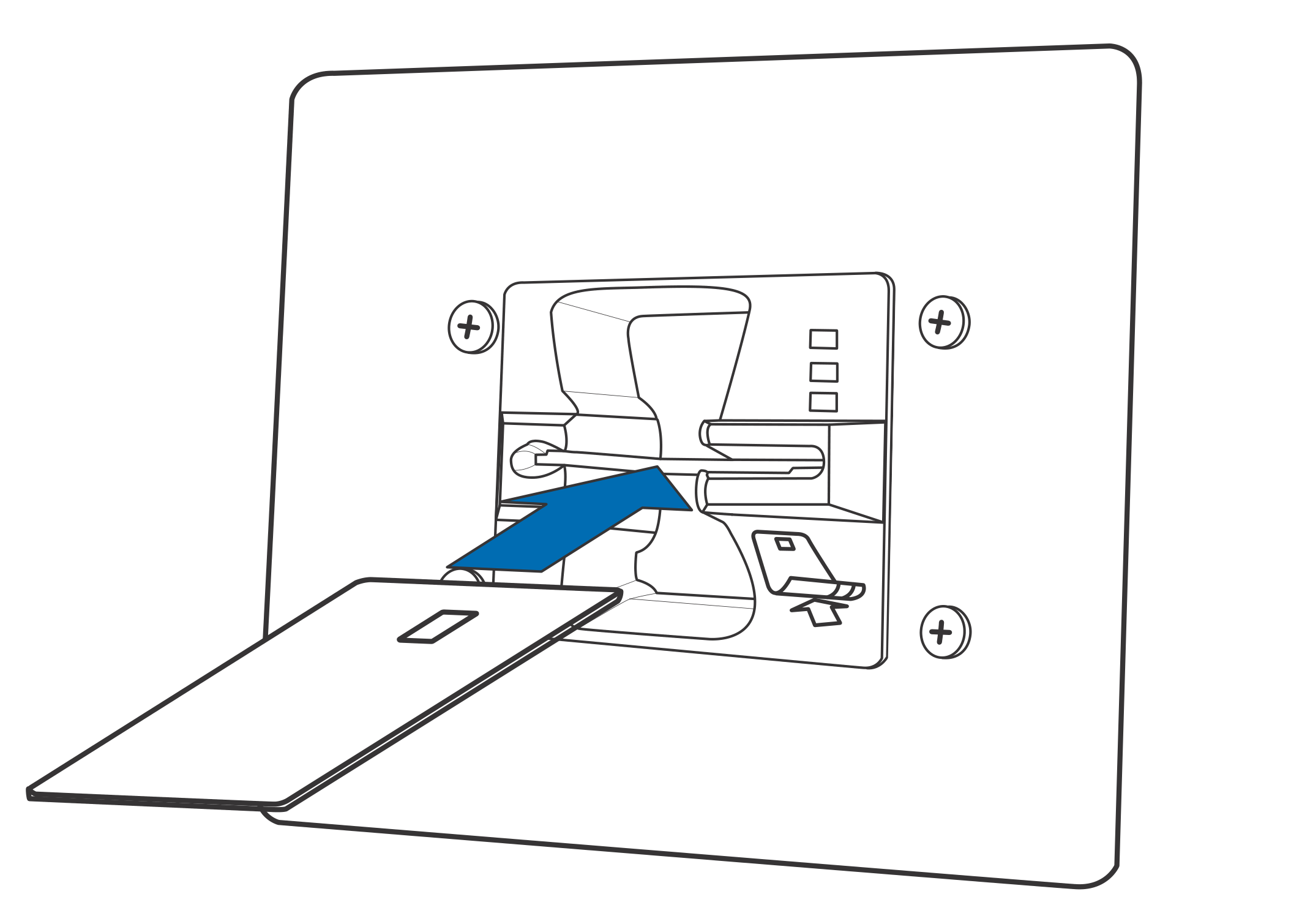
Position the card with the magnetic stripe facing downward and to the right of the card, or with the chip on top of the card and towards the card slot (see Figure 14).

If using a magnetic stripe card, insert the card fully into the slot, then remove the card in a smooth continuous motion.
You will lose transaction data files not yet stored in memory if there is a disruption in power supply during a transaction.
The LEDs or peripheral display will indicate if the transaction is complete.
If using a smart card, insert the card and follow the on-screen instructions before removing the card.
When using a smart card, leave the card in the reader until the transaction is complete.
Premature card removal can void the transaction.
Last updated
Was this helpful?