For the complete documentation index, see llms.txt. This page is also available as Markdown.

Device Setup

This chapter describes the setup procedure for the UX401 contactless reader.

Selecting Reader Location

Use the following guidelines when selecting a location for your reader:

  • Select a location convenient for the customer.

  • Select a location near the controlling device for the contactless unit.

Environmental Factors

The front panel of the device is dustproof and fade-proof. The UX401 is also water-resistant, in accordance with its IP65 ratings.

Unpacking the Shipping Carton

Open the shipping carton and carefully inspect its contents for possible tampering or shipping damage.

  1. Remove the items from the shipping carton. The standard package contains:

    • The UX401 contactless reader

    • One SMA (RF) coaxial cable

    • One RJ45 communication cable for connecting with the UX301 card reader.

    Refer to Accessories and Documentation for more information about related accessories.

  2. Remove any protective wrap before mounting the unit.

  3. Save the shipping carton and packing material for future repacking or moving of the device.

Examining the CTLS Reader Features

Before you continue the installation process, notice the features of the reader.

Figure 1: UX401 Front View

Front Functions

The front of the contactless device shows the following:

  • Customer-view indicator LEDs

  • The CTLS logo

  • Mounting stud holes

Figure 2: UX401 Rear View

Back Functions

The rear of the contactless device shows the following connectors:

  • RJ-45 host communication connector

  • SMA (RF) antenna connector

Connecting Unit to a Controlling Device

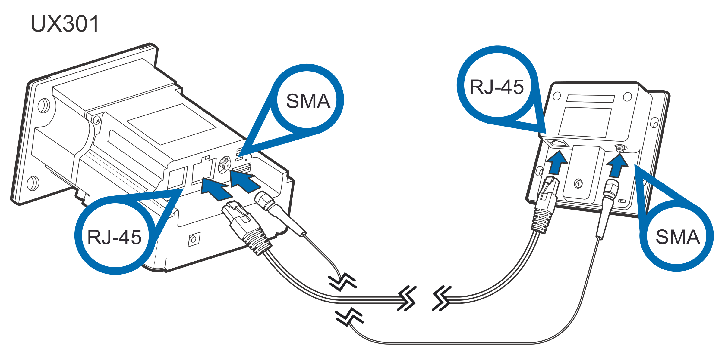
Use the following cables to connect the UX401 to the UX301 controlling device:

  • 8-pin RJ45 to RJ45 (VPN CBL159-313-02-A)

  • SMA cable, 0.8 m (VPN CBL159-302-03-A).

For EMVCo L1 compliance, please use the provided cables.

To connect to the UX301:

Both connections are necessary for using the UX401 contactless unit.

  1. Connect the RJ-45 plug to the rear of the UX401.

Figure 3: Connecting the UX401 to a Controlling Device
  1. Connect the 8-pin connector to the UX401 and the other to the UX301 port labeled "Ux401".

  2. Screw in the SMA connector to the ports of the UX401 and UX301.

To disconnect cables, use the same steps described above in reverse. If exchanging cables, use a Verifone-approved cable. See Accessories and Documentation for cable ordering information.

Contactless Support

This device supports the global contactless program specifications from American Express, MasterCard, Visa, Discover, ISIS SmartTap, and Google Wallet with virtually no changes to existing payment hardware or software.

Mounting the Reader

The UX401 is designed to be flush-mounted to the mounting surface, without further need for any external mounting devices.

Your mounting surface may have different installation instructions. Refer to your mounting device's user guide for further instructions.

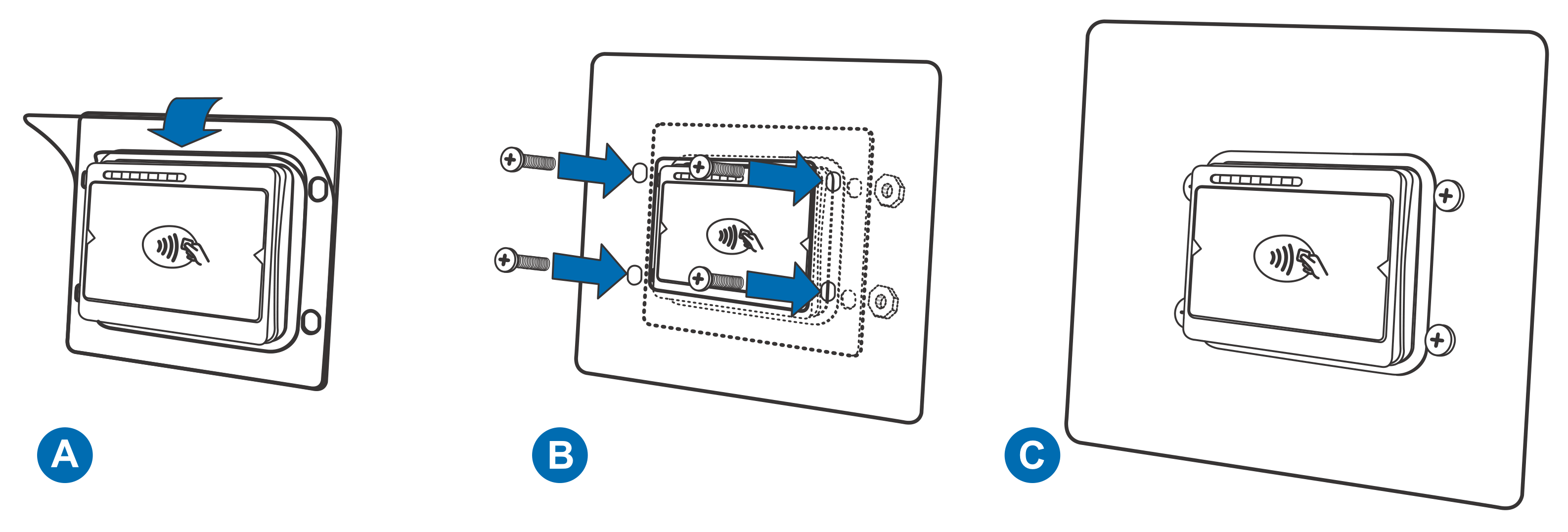
To mount the UX401:

  1. Peel off the plastic liner from the front of the unit.

Figure 4: Mounting the UX401
  1. Align the unit's stud holes with the stud holes of your mounting surface.

  2. Flush-mount the reader and secure the unit with M5 nuts.

Use M5 mounting studs with a minimum length of 12 mm.

Tighten the nuts using a recommended tightening torque of 7.0 kgfcm.

Using the Reader

The contactless reader is only active when signaled by an application for the start of a contactless card transaction.

When active, the UX401's contactless logo lights up.

Conducting a Contactless Transaction

To conduct a contactless transaction, hold the card (within 4 cm) or gently tap against the surface of the contactless antenna, marked by the logo.

Figure 5: Conducting a Contactless Transaction

The contactless unit uses various audible and visual confirmations to confirm transactions.

The actual audible and visual confirmations may vary depending on regional and customer requirements.

Last updated

Was this helpful?