> For the complete documentation index, see [llms.txt](https://docs.verifone.com/llms.txt). Markdown versions of documentation pages are available by appending `.md` to page URLs; this page is available as [Markdown](https://docs.verifone.com/hardware-products/hardware/petroleum-devices/c18-r2/c18-r2-installation-guide/device-setup.md).
# Device Setup
This chapter describes the setup and installation procedures for the **C18 R2** and includes the following sections:
* Environmental & Safety Guidelines
* Fire Hazard
* PIN Protection Measures
* Battery Pack Instructions
* Inside the Shipping Carton
* Device Features
* C18 R2 Installation and Configuration
## Environmental & Safety Guidelines
The C18 R2 should generally be installed on an easily accessible countertop. When selecting the installation location, ensure the following:
* Provide adequate ventilation around the unit.
* Ensure all cables can easily reach their respective connection points.
* Allow sufficient clearance for the cash drawer and cashier.
* Keep power cords away from direct foot-traffic paths.
Do not install the C18 R2 in locations exposed to:
* Direct sunlight
* Moisture
* Excessive dust
* Electrical noise or equipment that may cause significant voltage fluctuations, such as air conditioners, fans, or high-frequency security systems
{% hint style="info" %}
**NOTE:** Verifone strongly recommends connecting the C18 R2 to a 250 VA UPS with voltage regulation. Local regulations may require additional power-conditioning equipment at the installation site.
{% endhint %}
## Fire Hazard
{% hint style="danger" %}
**WARNING:** To reduce the risk of fire, keep the C18 R2 away from objects or equipment that generate excessive heat.
*Pour réduire le risque d'incendie, placer le C18 R2 à l'écart des objets ou équipements produisant une chaleur excessive.*
*Para reducir el riesgo de incendio, mantenga el C18 R2 alejado de objetos o equipos que generen un calor excesivo.*
{% endhint %}
## PIN Protection Measures
To help protect cardholder PIN confidentiality during PIN entry:
* Position the PINpad to prevent unauthorized observation of the PIN-entry process.
* Adjust the device angle to minimize the risk of shoulder surfing.
* Ensure in-store security cameras are positioned so that the PIN-entry keypad is not visible.
## Battery Pack Instructions
Dispose of the battery pack in accordance with all applicable national, state/provincial, and local laws and regulations. Where available, use authorized battery recycling or disposal facilities.
{% hint style="warning" %}
**CAUTION:** Risk of explosion if the battery is replaced with an incorrect or incompatible type.
*Éliminez la batterie conformément à toutes les lois et réglementations nationales, provinciales/régionales et locales applicables. Lorsque disponibles, utilisez les centres de recyclage ou d'élimination des batteries agréés.*
***ATTENTION :** Risque d'explosion si la batterie est remplacée par un modèle incorrect ou incompatible.*
*Deseche la batería de acuerdo con todas las leyes y regulaciones nacionales, estatales y locales aplicables. Cuando estén disponibles, utilice centros autorizados para el reciclaje o la eliminación de baterías.*
***PRECAUCIÓN:** Existe riesgo de explosión si la batería se reemplaza por un tipo incorrecto o incompatible.*
{% endhint %}
## Inside the Shipping Carton
Upon opening the shipping carton, meticulously examine its contents for any signs of tampering or shipping damage.
### To Unpack the Shipping Carton
{% stepper %}
{% step %}
#### Thoroughly examine the shipping carton
{% endstep %}
{% step %}
#### Verify the authenticity of the sender
Verify the authenticity of the sender by checking the shipping tracking number and other details on the product order paperwork.
{% endstep %}
{% step %}
#### Unseal the carton box
{% endstep %}
{% step %}
#### Inspect the carton contents
Conduct a detailed inspection of the shipping carton contents. The carton box includes the following components:
* 182-10X-01-NAA UNIT, C18 R2
* PWR182-002-01-A POWER SUPPLY
* CBL182-001-01-A POWER CORD, U.S.A
* PPL182-031-01-A CABLE COVER
* 23213-01-R CABLE, PRINTER POWER
* 23291-01-R CABLE, PRINTER DATA
* Software License
{% endstep %}
{% step %}
#### Remove the wrapping
Remove all the wrapping from the device and its components.
{% endstep %}
{% step %}
#### Peel off the clear protective film
Peel off the clear protective film from the display.
{% endstep %}
{% step %}
#### Preserve the shipping carton and packing materials
Preserve the shipping carton and packing materials for potential future repacking or relocation of the device.
{% endstep %}
{% endstepper %}
{% hint style="danger" %}
**WARNING:** Do not use a tampered or damaged unit. The device is equipped with tamper evident labels. If you observe any damage to a label or component, promptly inform both the shipping company and your Verifone service provider.
*N'utilisez pas un appareil trafiqué ou endommagé. L'appareil est équipé d'étiquettes d'inviolabilité. Si vous constatez des dommages sur une étiquette ou un composant, informez en rapidement la compagnie maritime et votre fournisseur de services Verifone.*
{% endhint %}
{% hint style="info" %}
**NOTE:** The cash drawer, thermal printer, keyboard, and Verifone M-Series PIN pad, which are part of the complete C18 R2 setup, can be ordered and are shipped separately.
{% endhint %}
## Device Features
Familiarize yourself with its key features.
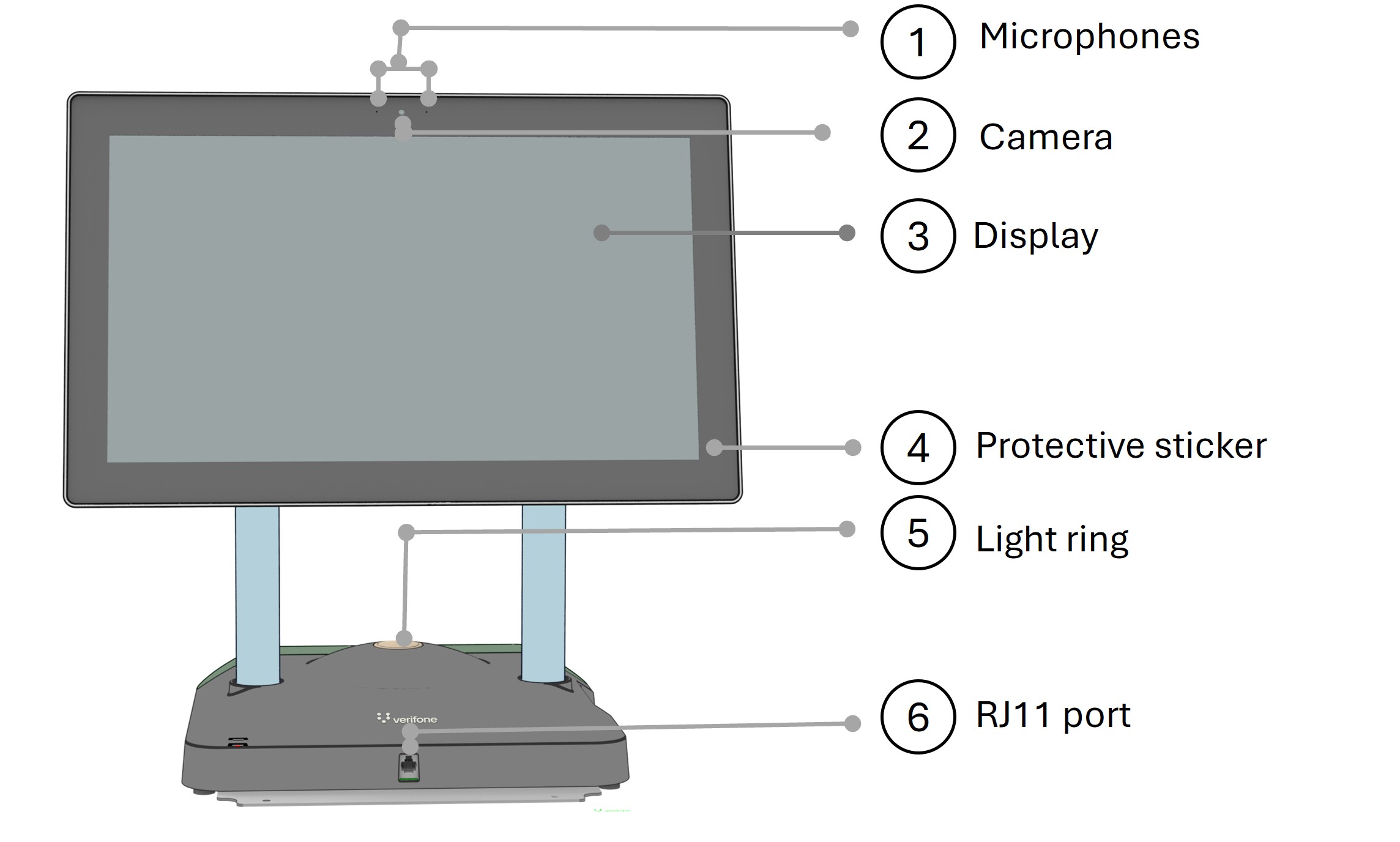
### Front Panel
1. **2 microphones**
2. **Camera**
3. **Display**
4. **Protective sticker**
5. **Light Ring** — The C18 R2 Light Ring is intended for Point-of-Sale (POS) devices and provides visual indicators for different functions.
6. **RJ11 port** — **This port is provided to connect the keyboard**
{% hint style="info" %}
**NOTE: Light Ring** — The C18 R2 Light Ring is intended for Point-of-Sale (POS) devices and provides visual indicators for different functions. It supports multiple colors and lighting styles to enhance usability and provide clear, intuitive status indications.
{% endhint %}
| Light Ring Color | Meaning |
| --------------------- | ------------------------------------------------ |
| **Green (Steady)** | Ready for customer use / transaction completed |
| **White (Steady)** | Active customer transaction in progress |
| **Blue (Steady)** | Cashier logged in |
| **Red (Flashing)** | Immediate cashier attention required |
| **Yellow (Flashing)** | Suspended, transferred, or abandoned transaction |
| **No Color** | Lane unavailable or not ready for customer use |
### C18 R2 Rear Panel
1. **Ethernet** — This port is provided to connect the C18 R2 to router
2. **Removable Magnetic cover** — This covers the rear ports on the C18
3. **Line out Audio**
4. **Microphone jack**
5. **COM ports**
6. **Cash drawer ports**
7. **USB ports**
8. **DC power**
9. **Printer power**
### Diagnostic Panel
The Diagnostic Panel is located on the right side of the C18 R2. Open the side interface cover to access it. From left to right, the panel includes:
**Battery Health:** Indicates the estimated remaining battery life.
* Blinking red: Less than 20% remaining.
* Solid red: 20%–50% remaining.
* Blinking green: Less than 50% remaining.
* Solid green: More than 50% remaining.
**Power LED:** Green when the C18 R2 is powered on.
**System Heartbeat LED:** Pulses on and off to indicate normal C18 R2 operation; displays red/green.
**Battery Charge:** Indicates available battery capacity.
* Green: Sufficient capacity for one or more graceful shutdowns.
* Red: Less than one graceful shutdown remains. Do not install software or disconnect power until the LED turns green.
* Blinking: Battery is charging.
* Solid: Battery is not charging.
**Status Window:** Displays system operating codes using a 7-segment or OLED display (2 × 7-segment/OLED).
**Diagnostic Switch Panel:** Four piano-style switches used to configure specific operating modes. Do not change the switch settings unless instructed by Verifone Technical Support.
**Console Port (RS-232):** For VASC use only; provides serial console access for debugging and system configuration.
**Reset Button:** Reboots the C18 R2 without removing power.
**Internal Speaker:** 2 speakers
## C18 R2 Installation & Configuration
### Network Configuration
#### One or Two C18 R2s
* Connect each C18 R2 to the **router** using an Ethernet cable.
* Connect Commander Site Server to the **router** using an Ethernet cable.
* Connect the router to the **corporate WAN/Intranet**.
Connect printers and cash drawers to the C18 R2 using **RS-232 cables**.
**Network path:**\
**C18 R2 → Router → Commander Site Server → Corporate WAN/Intranet**
#### More Than Two C18 R2s
* Connect each C18 R2 to a **network switch** using an Ethernet cable.
* Use a network switch with sufficient ports, typically **four or more**.
* Connect the network switch to the router using an Ethernet cable.
**Network path:**\
**C18 R2 → Network Switch → Router → Commander Site Server → Corporate WAN/Intranet**
### Rear Cable Cover
* **Remove:** Lift the corners of the Cable Cover.
* **Attach:** Press down on the corners until the cover is securely seated.
### C18 R2 Installation
Refer to **C18 R2 Rear Panel** for port locations.
{% stepper %}
{% step %}
#### Connect the printer serial cable
Connect one end of a shielded RS-232 cable to a **null modem adapter**. Connect the adapter to the Thermal Receipt Printer's serial port.
{% endstep %}
{% step %}
#### Connect the RS-232 cable to the C18 R2
Connect the other end of the RS-232 cable to **COM port** on the C18 R2.
{% endstep %}
{% step %}
#### Connect the printer power cable
Connect the printer power cable to the printer, with the flat side facing up.
Slide the connector down to lock or unlock the cable.
{% endstep %}
{% step %}
#### Connect printer power to the C18 R2
Connect the other end of the printer power cable to the C18 R2 **Printer Power** port until it locks securely.
{% endstep %}
{% step %}
#### Connect Ethernet
Connect an Ethernet cable to the C18 R2 **Ethernet** port and the other end to:
* **Router** — for one or two C18 R2s.
* **Network switch** — for more than two C18 R2s.
{% endstep %}
{% step %}
#### Connect the cash drawer
Connect the cash drawer cable to **Cash Drawer Port 1**. For two cash drawers, use **Ports 1 and 2**.
{% endstep %}
{% step %}
#### Connect the barcode scanner
Connect the barcode scanner to the C18 R2 either via USB or serial connection.
{% endstep %}
{% step %}
#### Connect the external PINpad
Connect the M-series external PINpad to the network switch via ethernet cable.
{% endstep %}
{% step %}
#### Connect the power brick
Connect the power brick to the C18 R2 **DC Power** port.
{% endstep %}
{% step %}
#### Connect AC power cord
Connect the AC power cord to the power brick and then to an appropriate electrical outlet.
{% endstep %}
{% endstepper %}
{% hint style="info" %}
**NOTE:**
1. **Scanner**: The customer can use their own scanner; both serial and USB connections are supported.
2. **Printers**: Printer can be connected to the C18 R2 either through RS232 (RP330) or through USB (RP700).
3. **Cash Drawer**: The C18 R2 provides **two shielded RJ-45/RJ-50 cash drawer ports;** the cash drawer can be connected to the C18 R2 through RS-232.
4. Com ports can be used to connect to many different peripherals and Verifone doesn't supply most of those.
{% endhint %}
#### Printer Cable Removal
Slide the connector's plastic outer cover downward to release the printer power cable. **Do not pull the cable**.
#### Printer Port Safety
{% hint style="danger" %}
**WARNING**: The printer port is **not a Limited Power Source (LPS)** as defined in Clause Q.1 of UL 62368-1. Printers connected to this port must comply with Clause 4.7 of UL 60950-1 or Clause 6.4 of UL 62368-1 and all applicable fire-enclosure requirements. Contact Verifone with any questions.
{% endhint %}
### Important Guidelines
* Power on the C18 R2 for **at least two hours before the initial application download** to prevent data loss and fully charge the battery.
* Do not obstruct the C18 R2 base, as this may restrict airflow.
* **RS-232 and Ethernet cables are not interchangeable** due to different pin configurations.
* Ensure the cash drawer **keyhole opening faces downward** when closing the drawer. Also, both cash drawers cannot be opened simultaneously.
### Keyboard Interface & Mounting
The keyboard is **application-dependent** and may not be included with all C18 R2 units. The C18 R2 has an **RJ11 serial port** on the front chassis for the 109-key external keyboard. Remove the protective Mylar film or rubber plug before connecting.
#### Installation
{% stepper %}
{% step %}
#### Secure the Keyboard Plate
Secure the Keyboard Plate (**P/N MET182-111-01-A**) to the C18 R2 base using two screws.
{% endstep %}
{% step %}
#### Remove the protective covering
Remove the protective covering from the RJ11 port on the C18 R2 base.
{% endstep %}
{% step %}
#### Connect the RJ11 cable
Connect the RJ11 cable between the keyboard and C18 R2.
{% endstep %}
{% step %}
#### Attach the keyboard
Attach the keyboard to the mounting/keyboard plate using its magnetic connection.
{% endstep %}
{% endstepper %}
The keyboard can be used **freestanding or mounted** on the metal plate. Magnetic pads and two locating pegs secure it and prevent sliding.
#### Keyboard Assembly Kit
* Keyboard
* Keyboard cable
* Keyboard mounting plate
* 2 mounting screws
### Display
The C18 R2 display has anti-glare and anti-fingerprint feature:
* Rotates between **portrait and landscape** orientations.
* Flips to a **customer-facing position** for self-checkout, where supported. It locks at right angles using a mechanical detent.
* Supports **multi-touch** functionality.
* Includes a **cashier-facing camera and microphone**.
---
# Agent Instructions
This documentation is published with GitBook. GitBook is the documentation platform designed so that both humans and AI agents can read, navigate, and reason over technical content effectively. Learn more at gitbook.com.
## Querying This Documentation
If you need additional information that is not directly available in this page, you can query the documentation dynamically by asking a question.
Perform an HTTP GET request on the current page URL with the `ask` query parameter, and the optional `goal` query parameter:
```
GET https://docs.verifone.com/hardware-products/hardware/petroleum-devices/c18-r2/c18-r2-installation-guide/device-setup.md?ask=&goal=
```
`ask` is the immediate question: it should be specific, self-contained, and written in natural language.
`goal` is optional and describes the broader end goal you are ultimately trying to accomplish on behalf of the user. GitBook uses it to tailor the answer towards what is most useful for that goal.
The response will contain a direct answer to the question and relevant excerpts and sources from the documentation.
Use this mechanism when the answer is not explicitly present in the current page, you need clarification or additional context, or you want to retrieve related documentation sections.